Why you need one
Most boats will be fitted with an electric bilge pump, usually with an external float switch or an internal water sensor so the pump automatically starts when the bilge water level rises. Automatic bilge pumps are left on when the boat is unattended so water will be pumped out automatically if there is a leak or excessive rainwater in the bilge. When you arrive back at the boat, how will you know whether the pump has been running? This How-to Guide shows you how to make a simple electronic bilge monitor.
There are optional additional features, such as a warning light and buzzer to tell you if the pump is running, as you may not know water is coming in otherwise!
You will need simple soldering skills, nothing more. The bilge monitor can be built into a project box as a complete unit, or the components can be wired behind a control panel on your boat.
Shopping list
The components can all be sourced from eBay, Maplins or similar retailers.
For the bilge monitor:
- a 12v LED panel lamp and panel mount
- a switch – rocker or toggle
- a reset button, which is a push switch “Normally Closed”
- a diode 1N 4001 or any generic diode 1A-3Amp
- relay DPDT with 12 Volt coil
- a medium size project box for stand-alone, or a small one if the switch and LED are to be mounted on an existing panel
- off-cuts of light gauge wire
To add a warning lamp and buzzer
- a second LED panel lamp and panel mount (different colour)
- a second switch
- a 12v buzzer
Your components will be something like this:

Construction
Simply cut lengths of wire and solder connections according to the diagram below. The diagram shows both the bilge monitor and bilge warning system combined. If you don’t want the warning system simply omit the buzzer, lamp and switch on the right, and connect the diode directly to the pump manual switch or float switch positive wire. The diode needs to be soldered with the bands nearest the relay. The relay shown here is a Rayex LMR2-12D from Maplins. Connect the Normally Open pins, ignore the Normally Closed pins. The view in the circuit diagram below is with the pins facing up. You can solder directly to the contacts, or a mount if available as some relays can be supplied with them.

Installation
You will need to run a positive wire directly from the battery via a 1amp fuse to the Battery Positive connection above. This is because it must be live even when the main battery switch is off – just as your automatic bilge pump has to be. Connect your Battery Negative to the nearest negative (ground) bus bar, and the Live from Bilge Pump must be connected to the pump side of the bilge manual or override switch. On most pumps, this becomes live when the pump is running as a result of the float or automatic switch closing – check if your pump does this. If not, wire it to the separate water level switch. If the pump has an integral switch and the override switch wire is not live when running, you will need a separate float switch in the bilge to alert the bilge monitor.
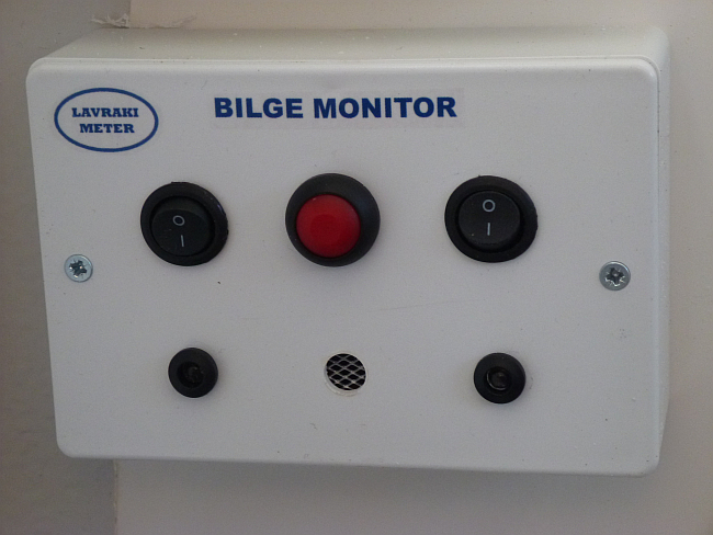
This is my bilge monitor, using a PB1 project box. I drilled a hole and stuck some alloy gauze behind it so the buzzer was not muffled. I used a flashing red LED for the monitor lamp and a steady amber LED for the bilge pump running warning. The buzzer is a beep style. I used water transfer for the label and logo, sprayed with cellulose fixative. In case you were wondering, Lavraki is the forum name for the person who designed the circuit for me.
Operation
When you are on the boat, switch the monitor off. The buzzer and warning lamp will show if the bilge pump is running. If the buzzer annoys you, you can mute it with the switch. When you leave the boat, switch the buzzer off and the monitor switch on. If when you return the lamp is lit, it shows the pump has been running while you were away. To switch the lamp off, press the reset button momentarily. If the monitor switch remains on, it will light again if the pump runs again.